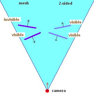
2 faces of a mesh (left) and of a 2-sided object (right), in a top view
top view of a surface facing L1
vs.1.1 //---------------------------------------------------------------------------------------- // vertex inputs //---------------------------------------------------------------------------------------- #define iPos v0 // vertex position #define iNormal v1 // vertex normal #define iTex0 v2 // base texture coordinates dcl_position iPos dcl_normal iNormal dcl_texcoord0 iTex0 //---------------------------------------------------------------------------------------- // constants //---------------------------------------------------------------------------------------- def c0, 0, 0, 0, 0 #define Zero c0 // c0 : 0;0;0;0 #define Matrix c10 // c10-c13 : matrix #define NFactor c14 // c14 : normal factor (-1 or +1) #define Ambient c15 // c15 : global ambient * material ambient #define MatDiff c16 // c16 : material diffuse color #define MatAlpha c16.w #define LightDiff1 c20 // c20 : light1 diffuse color #define LightDir1 c21 // c21 : light1 dir in model space #define LightDiff2 c30 // c30 : light2 diffuse color #define LightDir2 c31 // c31 : light2 dir in model space //---------------------------------------------------------------------------------------- // code //---------------------------------------------------------------------------------------- m4x4 oPos, iPos, Matrix // transform position mul r2, iNormal, NFactor // N or -N mov oT0.xy, iTex0 // copy tex coords // directional light 1 dp3 r0, r2, -LightDir1 // N * -LightDir1 max r0, r0, Zero // clamp to [0;1] mul r1, r0.x, MatDiff // * material diffuse mul r1, r1, LightDiff1 // * light1 diffuse // directional light 2 dp3 r0, r2, -LightDir2 // N * -LightDir2 max r0, r0, Zero // clamp to [0;1] mul r3, r0.x, MatDiff // * material diffuse mul r3, r3, LightDiff2 // * light2 diffuse // final color add r0, r1, r3 add oD0, r0, Ambient // + ambient mov oD0.w, MatAlpha // preserve alpha |
// protected data protected: bool m_bo2Sided; // DX9 access LPDIRECT3DDEVICE9 m_pDevice; LPDIRECT3D9 m_pD3D; // IB/VB LPDIRECT3DINDEXBUFFER9 m_pIB; LPDIRECT3DVERTEXBUFFER9 m_pVB; // vertex shader LPDIRECT3DVERTEXSHADER9 m_pVertexShader; LPDIRECT3DVERTEXDECLARATION9 m_pVertexDeclaration; LPD3DXCONSTANTTABLE m_pVertexConstants; LPDIRECT3DPIXELSHADER9 m_pPixelShader; LPD3DXCONSTANTTABLE m_pPixelConstants; // textures LPDIRECT3DTEXTURE9 m_pTexFront; LPDIRECT3DTEXTURE9 m_pTexBack; |
// vshader D3DVERTEXELEMENT9 decl[] = { { 0, 0, D3DDECLTYPE_FLOAT3, D3DDECLMETHOD_DEFAULT, D3DDECLUSAGE_POSITION, 0 }, { 0, 12, D3DDECLTYPE_FLOAT3, D3DDECLMETHOD_DEFAULT, D3DDECLUSAGE_NORMAL, 0 }, { 0, 24, D3DDECLTYPE_FLOAT2, D3DDECLMETHOD_DEFAULT, D3DDECLUSAGE_TEXCOORD, 0 }, D3DDECL_END() }; hrErr = m_pDevice->CreateVertexDeclaration(decl,&m_pVertexDeclaration); if(FAILED(hrErr)) { MessageBox(NULL,"CreateVertexDeclaration failed","CRendererDX9::Create",MB_OK|MB_ICONEXCLAMATION); return false; } DWORD dwFlags = 0; dwFlags |= D3DXSHADER_DEBUG; LPD3DXBUFFER pCode = NULL; LPD3DXBUFFER pErrors = NULL; hrErr = D3DXAssembleShaderFromFile("dx9/vshader.vsh",NULL,NULL,dwFlags,&pCode,&pErrors); if(pErrors) { char* szErrors = (char*)pErrors->GetBufferPointer(); pErrors->Release(); } if(FAILED(hrErr)) { MessageBox(NULL,"vertex shader creation failed","CRendererDX9::Create",MB_OK|MB_ICONEXCLAMATION); return false; } char* szCode = (char*)pCode->GetBufferPointer(); hrErr = m_pDevice->CreateVertexShader((DWORD*)pCode->GetBufferPointer(),&m_pVertexShader); pCode->Release(); if(FAILED(hrErr)) { MessageBox(NULL,"CreateVertexShader failed","CRendererDX9::Create",MB_OK|MB_ICONEXCLAMATION); return false; } |
TCHAR szVShader[] = _T("" "vs.1.1\n" "\n" "// vertex inputs\n" "\n" "#define iPos v0 // vertex position\n" "#define iNormal v1 // vertex normal\n" "#define iTex0 v2 // base texture coordinates\n" "\n" "dcl_position iPos\n" "dcl_normal iNormal\n" "dcl_texcoord0 iTex0\n" "\n" "// constants\n" "\n" [...etc...] "mov oD0.w, MatAlpha // preserve alpha"); |
hrErr = D3DXAssembleShader(szVShader,sizeof(szVShader),NULL,NULL,dwFlags,&pCode,&pErrors);
|
m4Total = m4Proj*m4View*m4World; m4Total.Transpose(); m_pDevice->SetVertexShaderConstantF(10,(float*)&m4Total,4); // trf matrix CVect4D v4NFactor(1.f); m_pDevice->SetVertexShaderConstantF(14,(float*)&v4NFactor,1); // normal factor CVect4D v4Ambient(0.25f,0.25f,0.25f,1.f); m_pDevice->SetVertexShaderConstantF(15,(float*)&v4Ambient,1); // ambient color CVect4D v4MatDiffuse(1.f,1.f,1.f,1.f); m_pDevice->SetVertexShaderConstantF(16,(float*)&v4MatDiffuse,1); // material diffuse // lights CVect4D v4LightDiffuse1(0.f,0.f,1.f,1.f); m_pDevice->SetVertexShaderConstantF(20,(float*)&v4LightDiffuse1,1); // light1 diffuse m4World.Invert(); CVect4D v4LightDir1(0.f,0.f,-1.f,0.f); v4LightDir1 = m4World*v4LightDir1; v4LightDir1.Normalize1(); m_pDevice->SetVertexShaderConstantF(21,(float*)&v4LightDir1,1); // light1 direction CVect4D v4LightDiffuse2(1.f,0.f,0.f,1.f); m_pDevice->SetVertexShaderConstantF(30,(float*)&v4LightDiffuse2,1); // light2 diffuse CVect4D v4LightDir2(0.f,0.f,1.f,0.f); v4LightDir2 = m4World*v4LightDir2; v4LightDir2.Normalize1(); m_pDevice->SetVertexShaderConstantF(31,(float*)&v4LightDir2,1); // light2 direction |
m_pDevice->SetVertexDeclaration(m_pVertexDeclaration); m_pDevice->SetVertexShader (m_pVertexShader); m_pDevice->SetPixelShader (m_pPixelShader); m_pDevice->SetStreamSource (0,m_pVB,0,sizeof(VERTEX_SIMPLE)); m_pDevice->SetIndices ( m_pIB); m_pDevice->SetTexture (TextureIndex,m_pTexFront); D3DPRIMITIVETYPE Type = D3DPT_TRIANGLELIST; HRESULT hrErr = m_pDevice->DrawIndexedPrimitive(Type,0,0,4,0,2); // 4 vtx, 2 tris if(FAILED(hrErr)) return hrErr; |
float4x4 Matrix; float4 NFactor; float4 Ambient; float4 MatDiff; float4 LightDiff1; float4 LightDir1; float4 LightDiff2; float4 LightDir2; struct VS_INPUT { float4 Pos : POSITION; float4 Normal : NORMAL; float2 Tex0 : TEXCOORD0; }; struct VS_OUTPUT { float4 Pos : POSITION; float4 Color : COLOR; float2 Tex0 : TEXCOORD0; }; //////////////////////////////////////// VS_OUTPUT VShade(VS_INPUT In) { VS_OUTPUT Out = (VS_OUTPUT) 0; Out.Pos = mul(Matrix,In.Pos); Out.Tex0 = In.Tex0; float4 Normal = In.Normal*NFactor; // N or -N // directional light 1 float4 Color1 = max(0,dot(Normal,-LightDir1)) *MatDiff*LightDiff1; // directional light 2 float4 Color2 = max(0,dot(Normal,-LightDir2)) *MatDiff*LightDiff2; // final color Out.Color = Color1+Color2+Ambient; Out.Color.a = MatDiff.a; return Out; } |
static float4 GlobalVar; static const float SpecPower = 64.f; |
inline float4 DirectionalLight(float4 Normal,float4 Dir,float4 Diffuse) { return max(0,dot(Normal,-Dir))*Diffuse; } VS_OUTPUT VShade(VS_INPUT In) { VS_OUTPUT Out = (VS_OUTPUT) 0; Out.Pos = mul(Matrix,In.Pos); Out.Tex0 = In.Tex0; float4 Normal = In.Normal*NFactor; // N or -N Out.Color = Ambient+DirectionalLight(Normal,LightDir1,LightDiff1)*MatDiff +DirectionalLight(Normal,LightDir2,LightDiff2)*MatDiff; Out.Color.a = MatDiff.a; return Out; } |
hrErr = D3DXCompileShaderFromFile("dx9/vshader.fx",NULL,NULL,"VShade","vs_1_1",dwFlags,&pCode,&pErrors,&m_pVertexConstants); |
if(m_pVertexConstants) { D3DXHANDLE handle; if(handle = m_pVertexConstants->GetConstantByName(NULL,"Matrix")) m_pVertexConstants->SetMatrix(m_pDevice,handle,(D3DXMATRIX*)&m4Total); if(handle = m_pVertexConstants->GetConstantByName(NULL,"NFactor")) m_pVertexConstants->SetVector(m_pDevice,handle,(D3DXVECTOR4*)&v4NFactor); if(handle = m_pVertexConstants->GetConstantByName(NULL,"Ambient")) m_pVertexConstants->SetVector(m_pDevice,handle,(D3DXVECTOR4*)&v4Ambient); if(handle = m_pVertexConstants->GetConstantByName(NULL,"MatDiff")) m_pVertexConstants->SetVector(m_pDevice,handle,(D3DXVECTOR4*)&v4MatDiffuse); // lights if(handle = m_pVertexConstants->GetConstantByName(NULL,"LightDiff1")) m_pVertexConstants->SetVector(m_pDevice,handle,(D3DXVECTOR4*)&v4LightDiffuse1); if(handle = m_pVertexConstants->GetConstantByName(NULL,"LightDir1")) m_pVertexConstants->SetVector(m_pDevice,handle,(D3DXVECTOR4*)&v4LightDir1); if(handle = m_pVertexConstants->GetConstantByName(NULL,"LightDiff2")) m_pVertexConstants->SetVector(m_pDevice,handle,(D3DXVECTOR4*)&v4LightDiffuse2); if(handle = m_pVertexConstants->GetConstantByName(NULL,"LightDir2")) m_pVertexConstants->SetVector(m_pDevice,handle,(D3DXVECTOR4*)&v4LightDir2); } |
sampler baseTex; struct PS_INPUT { float4 Color : COLOR0; float2 Tex0 : TEXCOORD0; }; struct PS_OUTPUT { float4 Color : COLOR; }; //////////////////////////////////////// PS_OUTPUT PShade(PS_INPUT In) { PS_OUTPUT Out = (PS_OUTPUT) 0; Out.Color = In.Color * tex2D(baseTex,In.Tex0); return Out; } |
// pshader hrErr = D3DXCompileShaderFromFile("dx9/pshader.fx",NULL,NULL,"PShade","ps_1_1",dwFlags,&pCode,&pErrors,&m_pPixelConstants); if(pErrors) { char* szErrors = (char*)pErrors->GetBufferPointer(); pErrors->Release(); } if(FAILED(hrErr)) { MessageBox(NULL,"pixel shader creation failed","CRendererDX9::Create",MB_OK|MB_ICONEXCLAMATION); return false; } szCode = (char*)pCode->GetBufferPointer(); hrErr = m_pDevice->CreatePixelShader((DWORD*)pCode->GetBufferPointer(),&m_pPixelShader); pCode->Release(); if(FAILED(hrErr)) { MessageBox(NULL,"CreatePixelShader failed","CRendererDX9::Create",MB_OK|MB_ICONEXCLAMATION); return false; } |
    if(m_pPixelConstants && (handle = m_pPixelConstants->GetConstantByName(NULL,"baseTex")))
      {
      D3DXCONSTANT_DESC constDesc;
      UINT count = 1;
      m_pPixelConstants->GetConstantDesc(handle,&constDesc,&count);

      if(constDesc.RegisterSet == D3DXRS_SAMPLER)
        TextureIndex = constDesc.RegisterIndex;
      }
|
m_pDevice->SetTexture(TextureIndex,m_pTexFront); |
PS_OUTPUT PShade(PS_INPUT In) { PS_OUTPUT Out = (PS_OUTPUT) 0; Out.Color = In.Color * tex2D(baseTex,In.Tex0); float fIntensity = Out.Color.r*0.30f + Out.Color.g*0.59f + Out.Color.b*0.11f; Out.Color = float4(fIntensity,fIntensity,fIntensity,1.f); return Out; } |
fxc /T:vs_2_0 /E:VShade /Zi /Fc:vshader.fxc vshader.fx fxc /T:ps_2_0 /E:PShade /Zi /Fc:pshader.fxc pshader.fx |
// // Generated by Microsoft (R) D3DX9 Shader Compiler // // Source: vshader.fx // Flags: /E:VShade /T:vs_2_0 /Zi // // Parameters: // // float4x4 Matrix; // float4 NFactor; // float4 Ambient; // float4 MatDiff; // float4 LightDiff1; // float4 LightDir1; // float4 LightDiff2; // float4 LightDir2; // // // Registers: // // Name Reg Size // ------------ ----- ---- // Matrix c0 4 // NFactor c4 1 // Ambient c5 1 // MatDiff c6 1 // LightDiff1 c7 1 // LightDir1 c8 1 // LightDiff2 c9 1 // LightDir2 c10 1 // vs_2_0 def c11, 0, 0, 0, 0 dcl_position v0 // In<0,1,2,3> dcl_normal v1 // In<4,5,6,7> dcl_texcoord v2 // In<8,9> #line 32 "C:\temp\fairyengine\vshader.fx" mul r0, v0.x, c0 mad r2, v0.y, c1, r0 mad r4, v0.z, c2, r2 mad oPos, v0.w, c3, r4 // ::VShade<0,1,2,3> mul r1, v1, c4 // Normal<0,1,2,3> #line 38 dp4 r8.w, r1, -c8 max r3.w, r8.w, c11.x mul r10.xyz, r3.w, c6 mul r5.xyz, r10, c7 // Color1<0,1,2> #line 42 dp4 r5.w, r1, -c10 max r5.w, r5.w, c11.x mul r7.xyz, r5.w, c6 #line 46 mad r9.xyz, r7, c9, r5 add oD0.xyz, r9, c5 // ::VShade<4,5,6> mov oD0.w, c6.w // ::VShade<7> #line 33 mov oT0.xy, v2 // ::VShade<8,9> // approximately 16 instruction slots used // 0000: fffe0200 0098fffe 47554244 00000028 _......_DBUG(___ // 0010: 00000244 00000000 00000001 00000048 D.______.___H___ [etc...] |
|
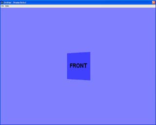
front facing quad
|
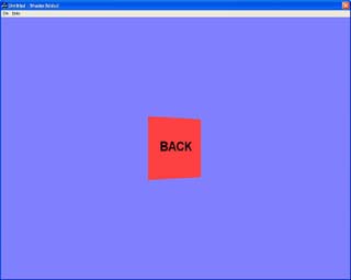
back facing quad
|
front texture

|
back texture

|